On this tutorial, you’ll discover ways to add a bootloader in a newly bought ATmega328P IC, and add code in ATmega328P, ATtiny85, and ATmega8 utilizing Arduino UNO board.
In some Arduino initiatives, you could solely need to use the microcontroller IC(ATmega328P) as a substitute of utilizing the entire Arduino UNO board. In that case both you may take away the ATmega328P IC from the Arduino UNO board and use it with a minimal circuit or you should buy a brand new ATmega328P IC and add code in it and use it in your venture.
Whereas a few of the Arduino initiatives don’t require a strong microcontroller like ATmega328P so, at the moment put in of utilizing the Arduino UNO board or ATmega328P IC, you should utilize ATtiny85. On this tutorial, you’ll study all this stuff.
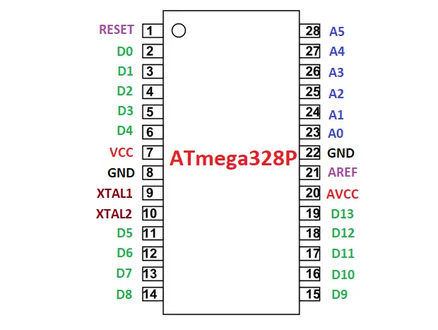
Pin configuration of ATmega328P IC
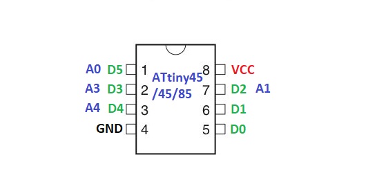
Pin configuration of ATtiny25/45/85
ATmega328P on a breadboard or standalone ATmega328P
Right here, we are going to use the identical ATmega328P IC that’s current within the Arduino UNO board.
Step1: Add your code to the Arduino Board. I’ve uploaded an LED blinking code in my case.
Step3: Take away the ATmega328P from the Arduino UNO board and insert it onto the breadboard.
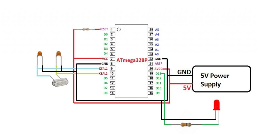
Step2: Create a minimal circuit that’s required for the ATmega328P IC. Check with determine 1.3.
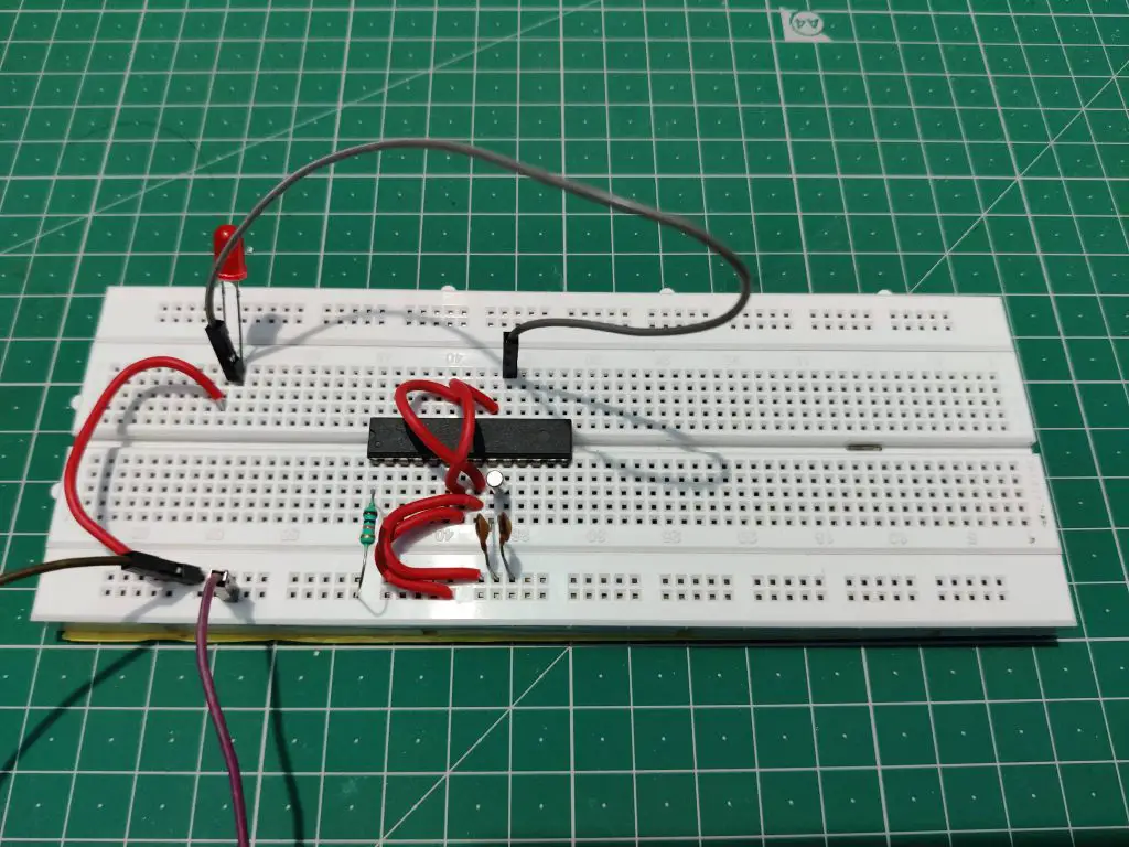
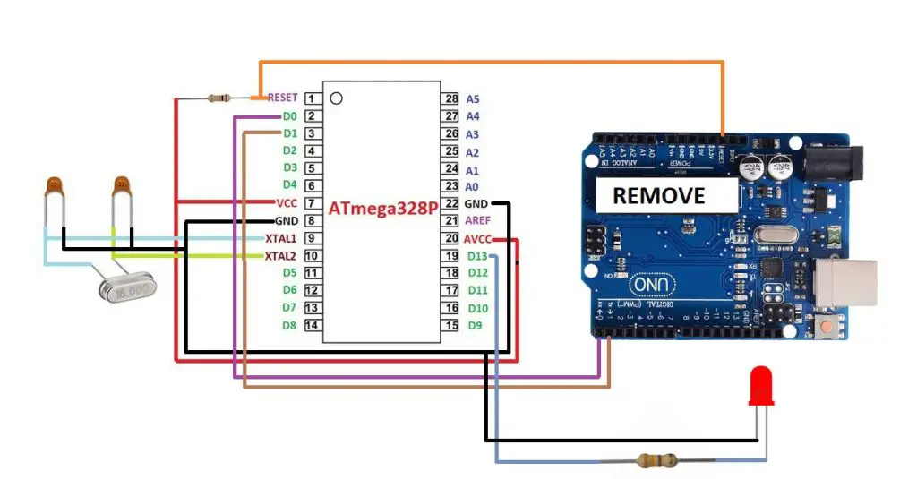
Step3: Join all of your modules or sensors or any digital elements to the ATmega328P IC that you simply need to use in your venture. I’m making a LED blink venture so, I’ve linked an LED on the D3 pin of the ATmega328P. See determine 1.4. The pins marked on the Arduino UNO board are completely different on the ATmega328P IC. Check with Determine 1.1 for pin configuration of ATmega328P IC.
Step4: Give energy to the circuit utilizing a 5V adapter.
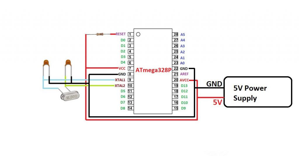
Capacitors: 22pF Crystal: 16MHz
Capacitors: 22pF Crystal: 16MHz Resistor: 330 Ohm
Add bootloader in ATmega328P IC
In case you need to use a brand new ATmega328P IC in your venture then it’s a must to observe the next steps.
Step1: Create a minimal circuit for the newly bought ATmega328P IC as proven in determine 1.3.
Step2: Go to the File tab then click on on examples then click on on ArduinoISP.
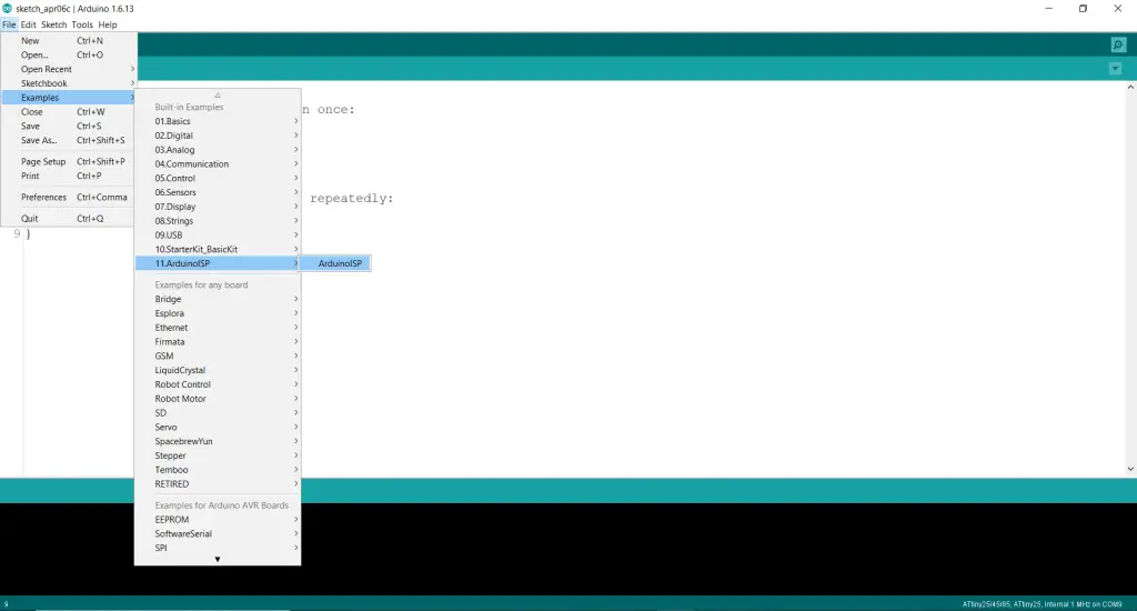
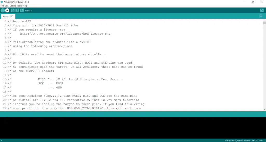
Step3: Add this ArduinoISP code to your Arduino UNO Board.
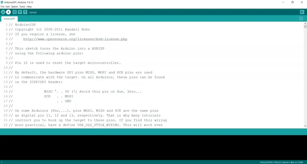
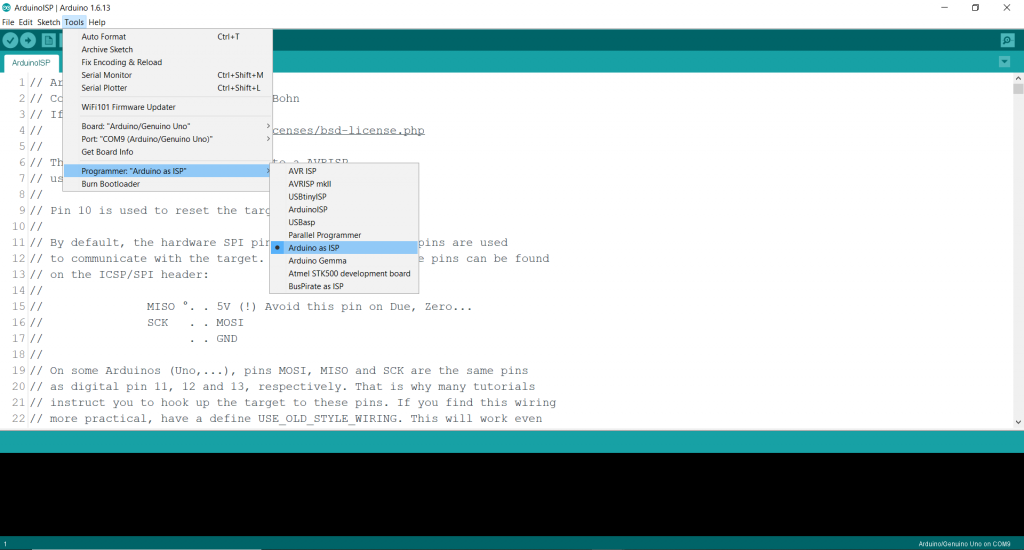
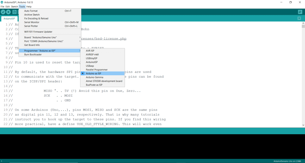
Step4: After the ArduinoISP code is uploaded, go to the Instruments tab after which go to the Programmer choice and choose Arduino as ISP.
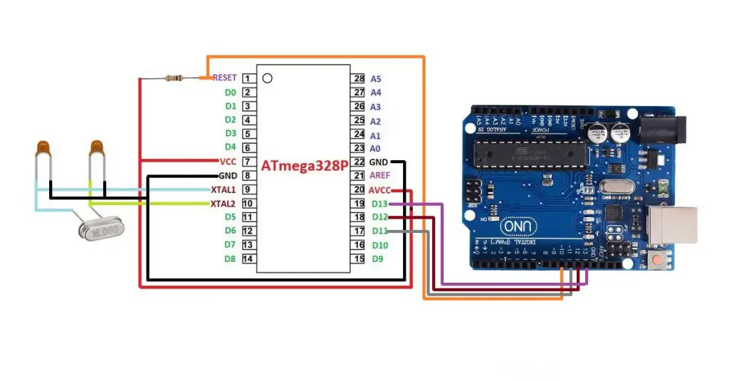
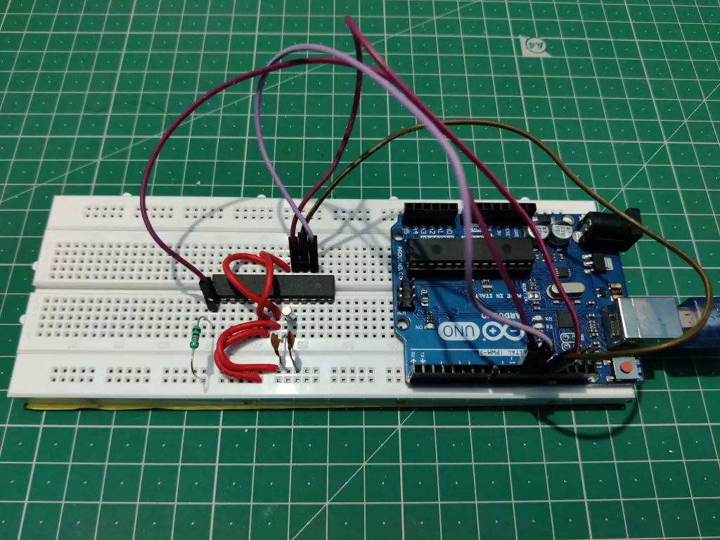
Step5: Join the ATmega328P IC with the Arduino UNO board as proven in Determine 1.4.
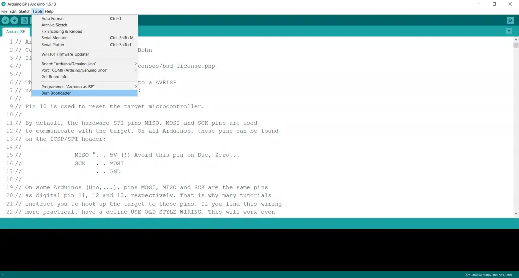
Step6: Go to the Instruments tab once more after which click on on burn bootloader.
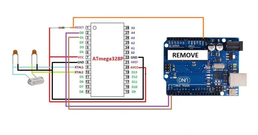
Step7: The bootloader is burned within the IC. Now, you should utilize it to add code in it. For that take away the primary microcontroller IC from the Arduino UNO board and join the brand new ATmega328P IC as proven within the determine.
Step8: Add your code to the brand new IC. I’m importing an LED blinking code. Ensure you have chosen the suitable port and board(Arduino UNO).
ATmega328P IC minimal circuit clarification
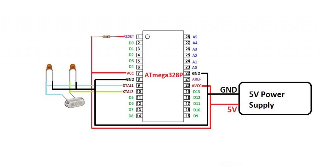
The circuit proven within the determine is the minimal circuit that’s required to work with standalone ATmega328P IC.
Pin 1 is the RESET pin used for resetting the microcontroller. You will have join a pull-up resistor to this pin as a result of the microcontroller resets when its get a logic LOW sign.
Pin 7 and Pin 20 are VCC pin it’s a must to join 5V right here.
Pin 8 and Pin 22 are GND pin it’s a must to join GND right here.
Pin 9 and Pin 10 are used for connecting exterior crystal of 16MHz together with two 22pF capacitors.
Programming ATtiny24/44/84/25/45/85 with Arduino UNO
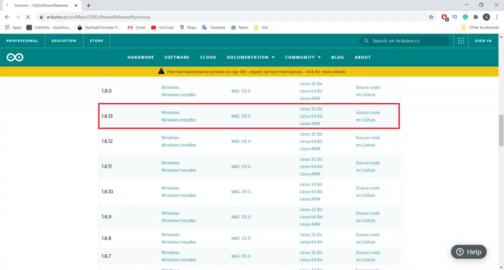
Setp1: Open Arduino.cc web site and obtain Arduino 1.6.1. The newer variations won’t work for this objective.
Step2: Set up Arduino 1.6.1 in your desktop/laptop computer.
Step2: Go to the File tab then click on on examples after which click on on ArduinoISP.
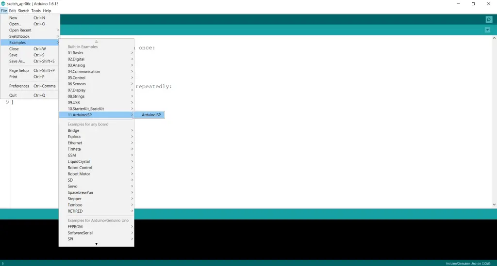
Step3: Add this ArduinoISP code to your Arduino UNO Board.
Step4: After the ArduinoISP code is uploaded, go to the Instruments tab after which go to the Programmer choice and choose Arduino as ISP.
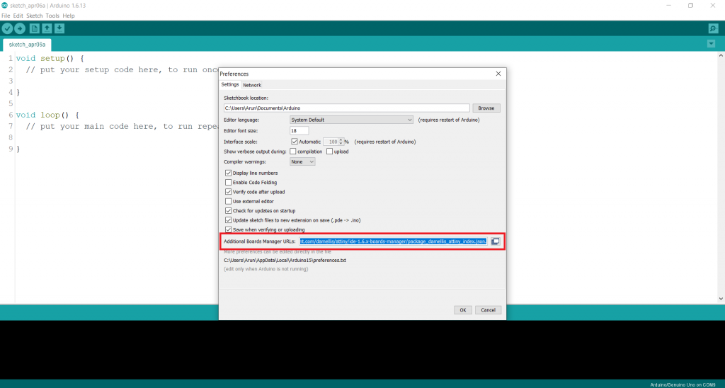
Step5: Go to the File tab, then click on on preferences. Copy and paste this hyperlink in “Further Board Supervisor URLs https://uncooked.githubusercontent.com/damellis/attiny/ide-1.6.x-boards-manager/package_damellis_attiny_index.json
Step6: Go to the Instruments tab then click on on board then click on on Board supervisor. The board supervisor will open.
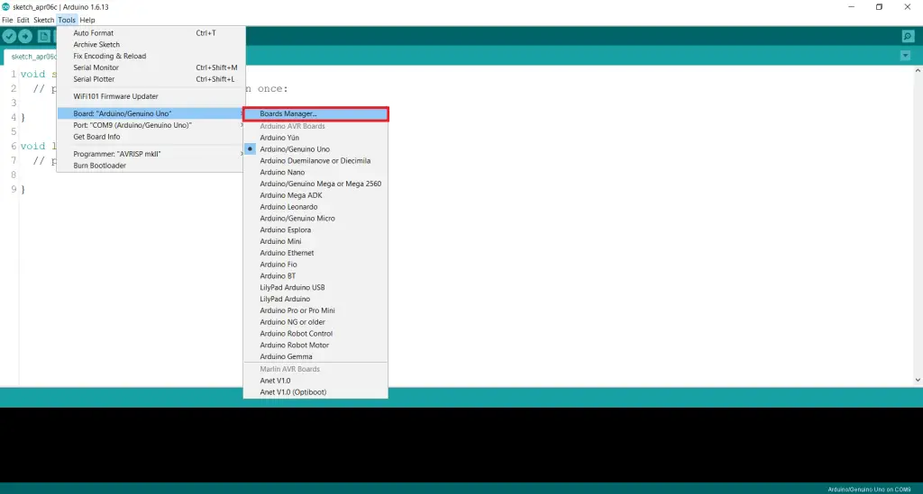
Step7: Watch for a while after which scroll down. You’ll this selection. Click on on set up.
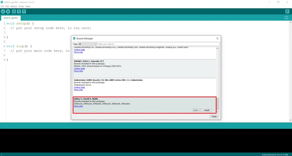
Step8. The boards are put in.
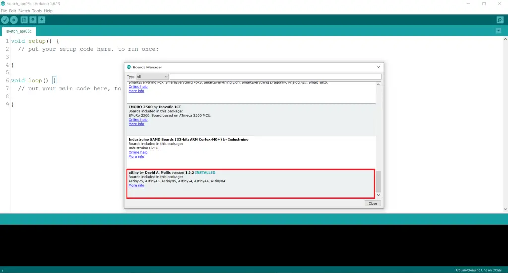
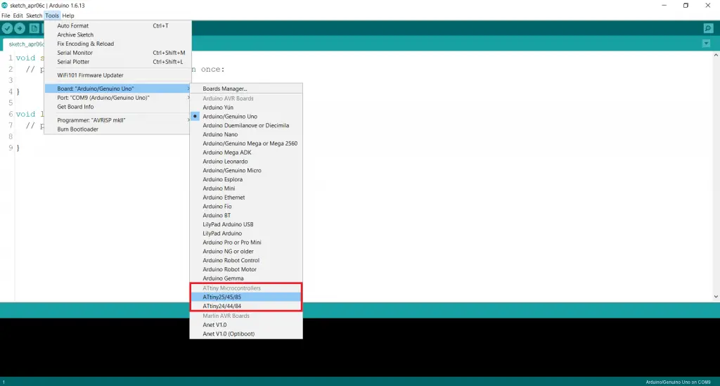
Step9: Go to the Instruments tab once more. Click on on boards and you will note two extra choices. Choose ATtiny25/45/85.
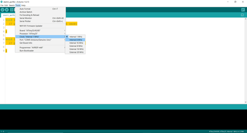
Step10: From the Instruments tab set the Inner clock to 8MHz.
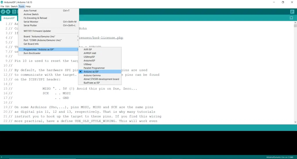
Step11: From the Instruments tab choose Arduino programmer as ISP
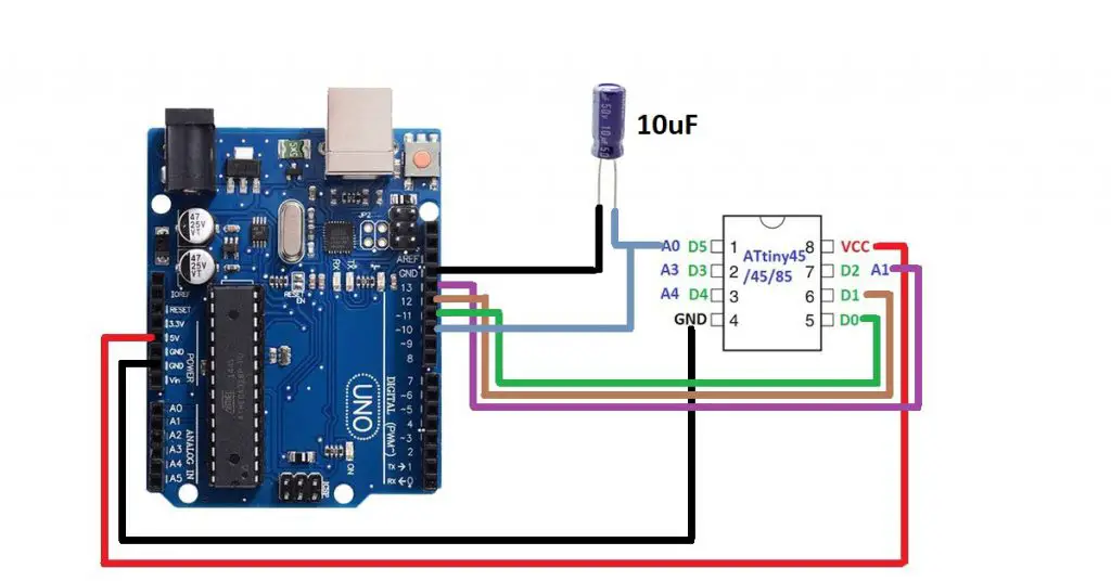
Step12: Join the ATtiny85 IC to the Arduino UNO as proven within the determine 1.7
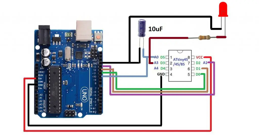
Step13.Add your code to the brand new IC. I’m importing an LED blinking code. Ensure you have chosen the suitable port and board(Arduino UNO).
Programming ATmega8 with Arduino UNO
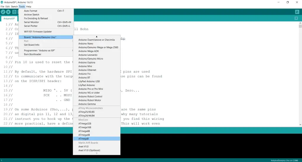
You need to observe all of the steps that you’ve adopted for programming ATtiny IC with Arduino UNO board. The one distinction is that it’s a must to paste this hyperlink within the Further Board URls and Set up MiniCore from the board supervisor. https://mcudude.github.io/MiniCore/package_MCUdude_MiniCore_index.json
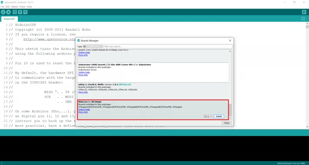
Then choose ATmega8 from the board. Remainder of the steps are the identical as that of the ATtiny
